|
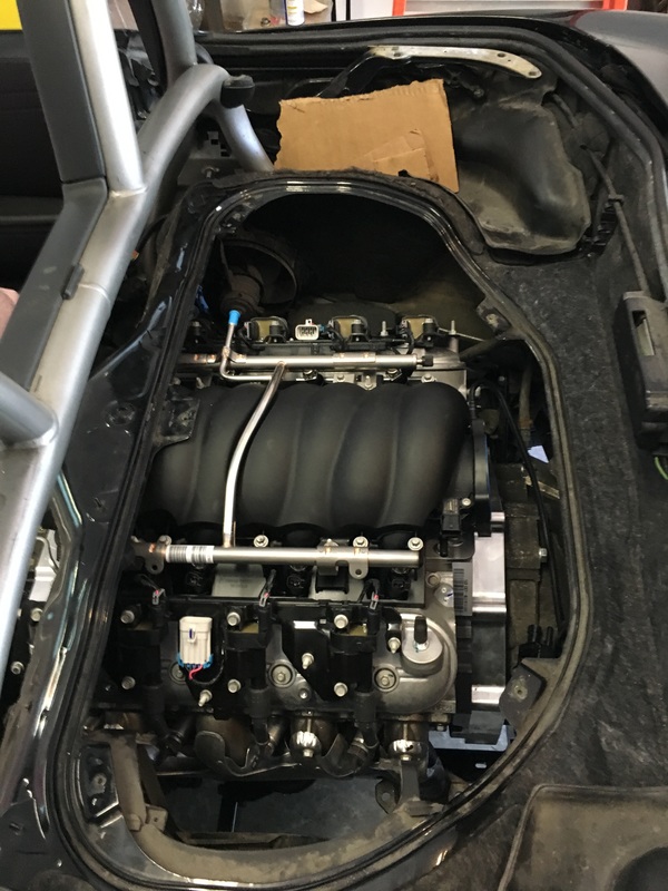
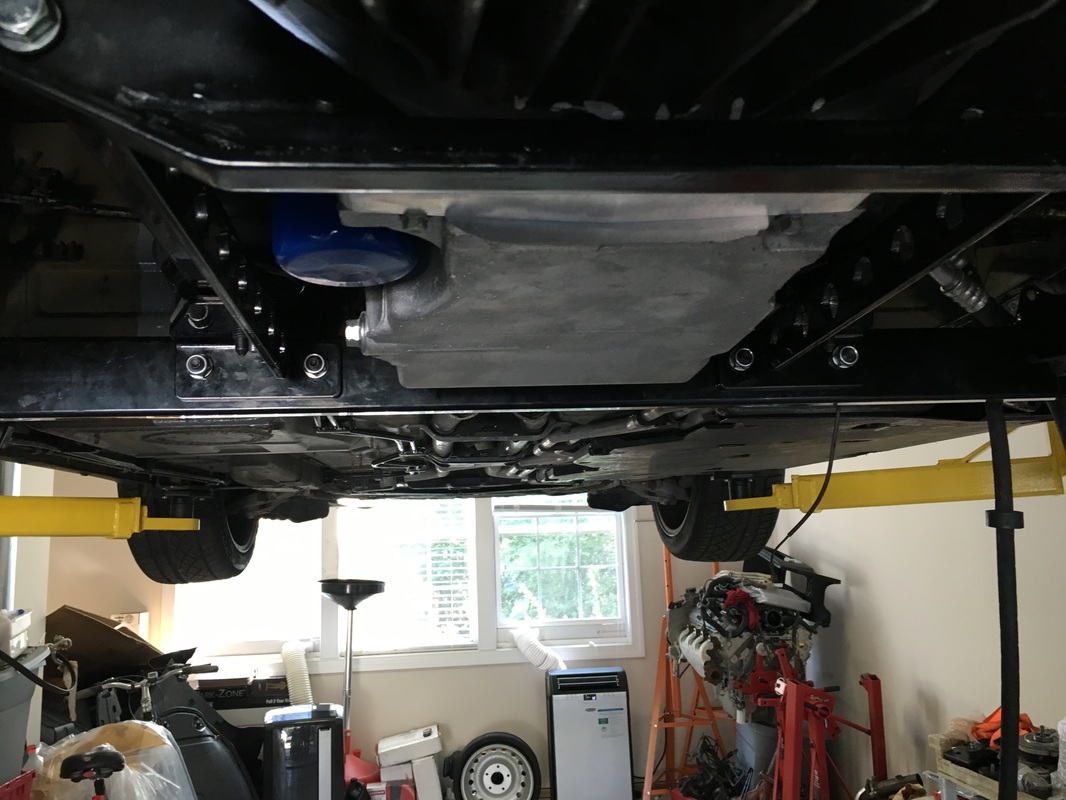
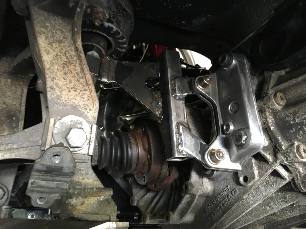
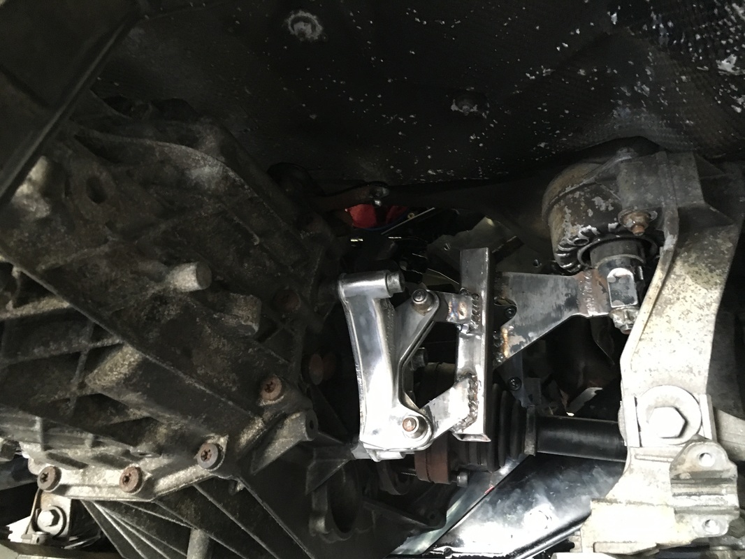
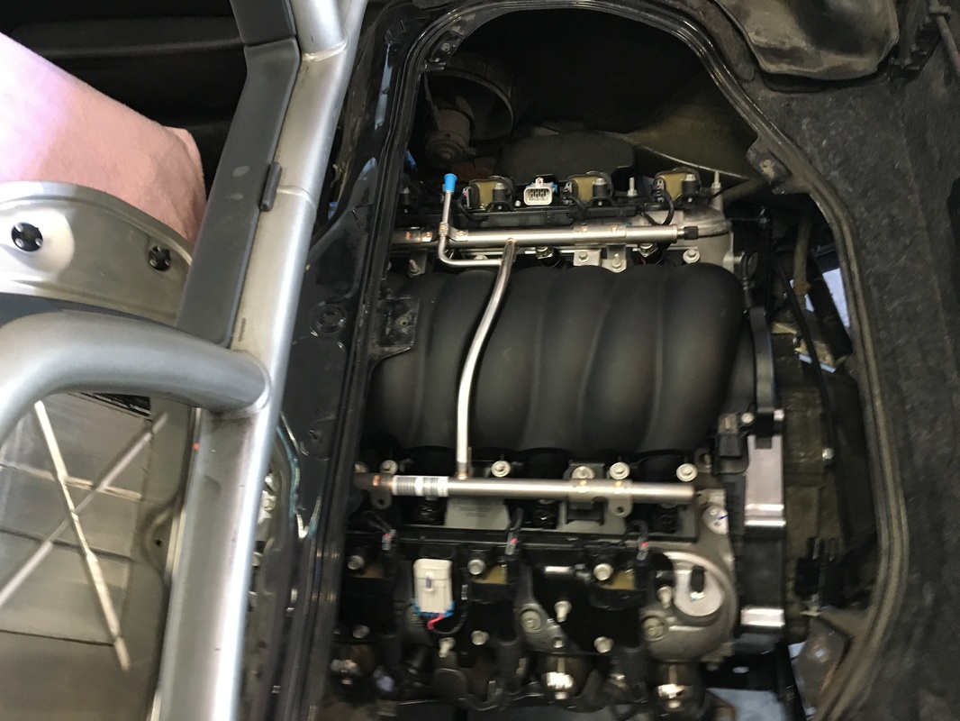
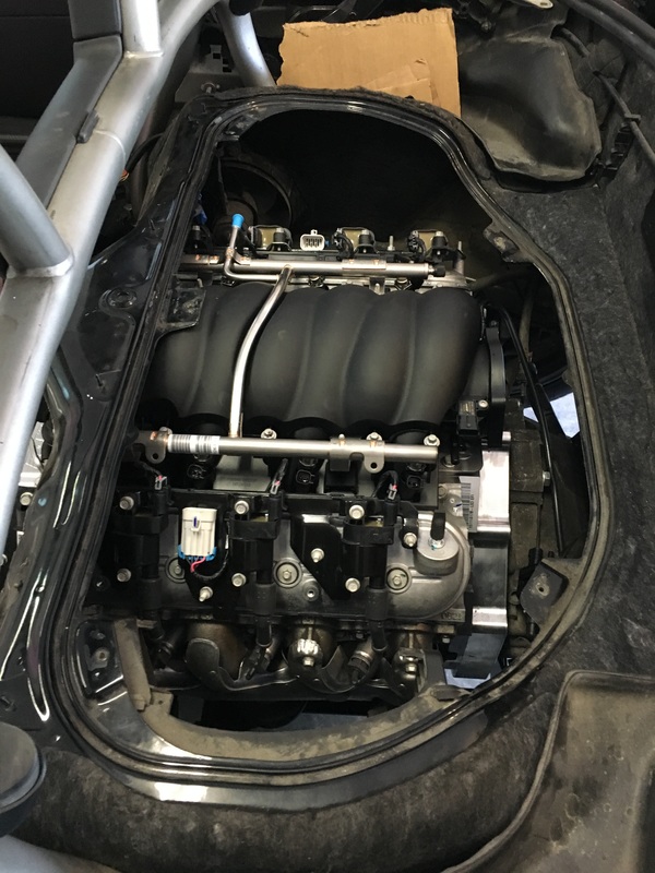
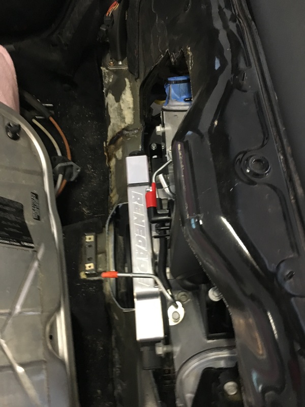
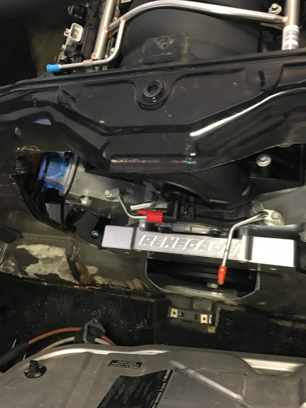
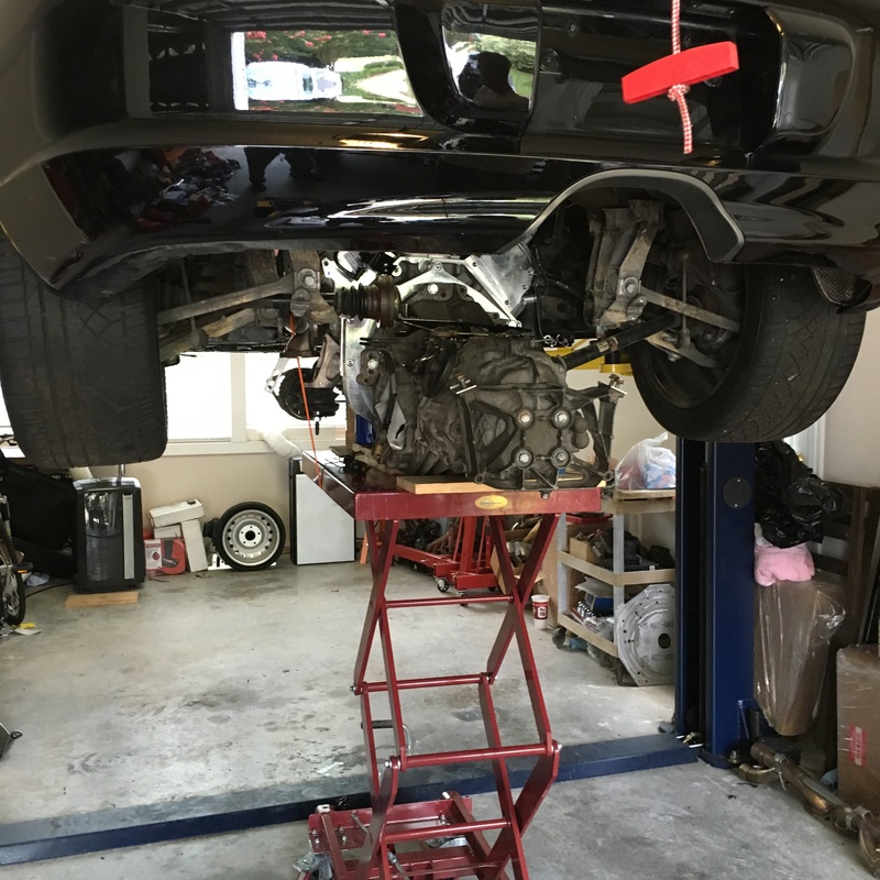
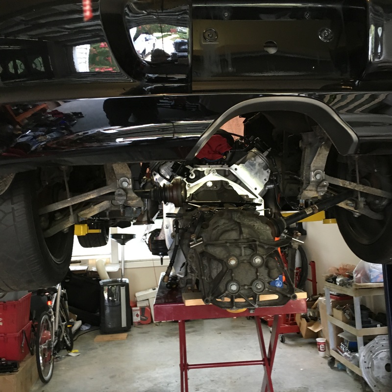
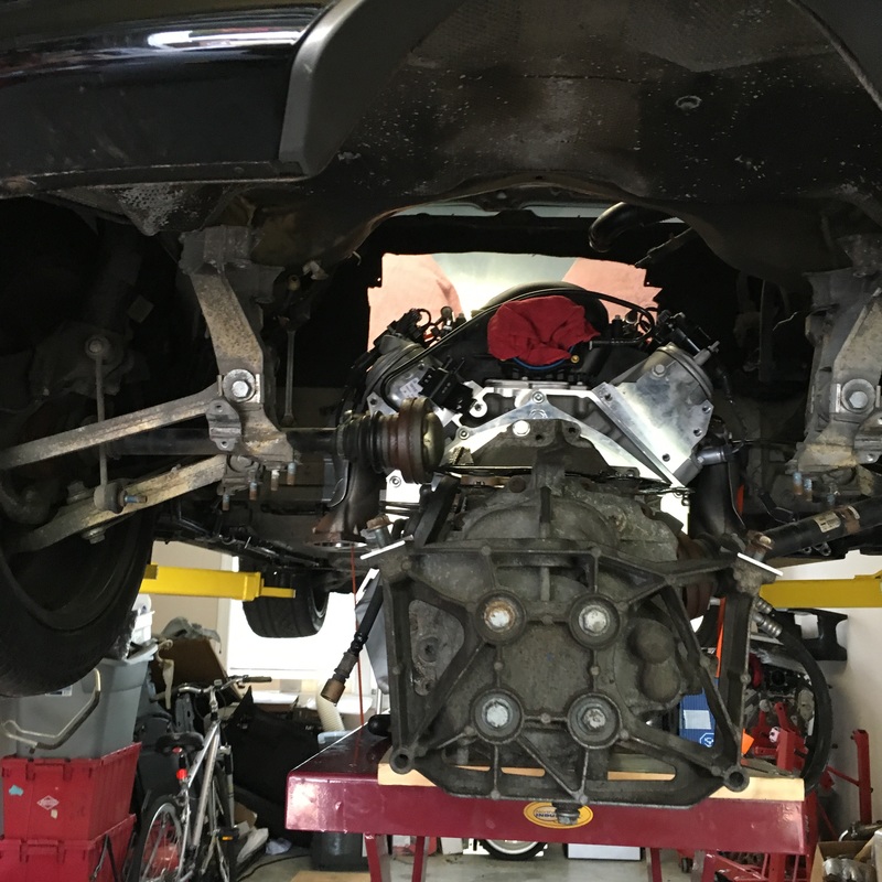
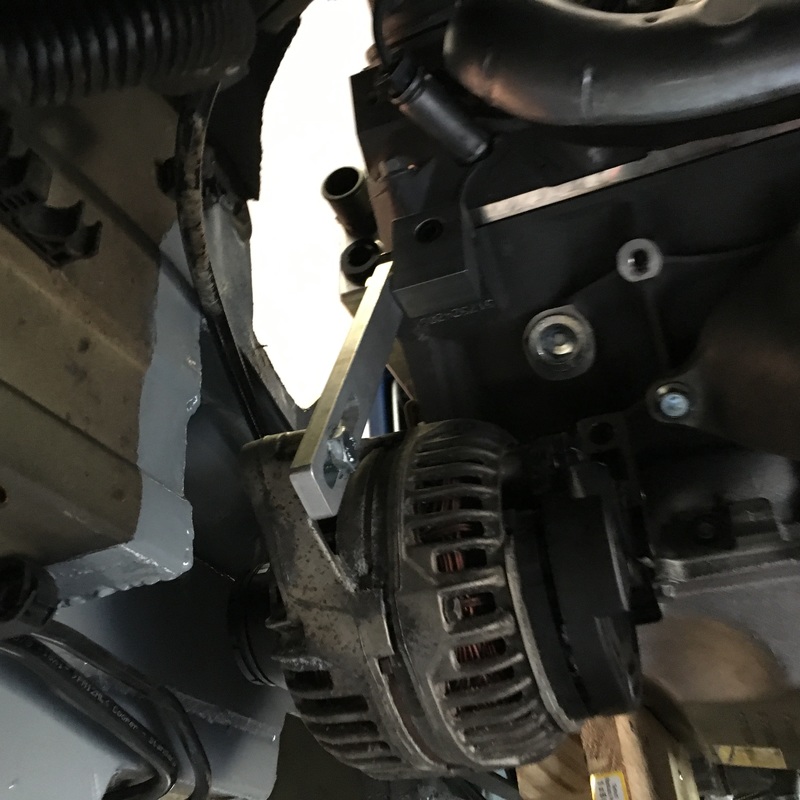
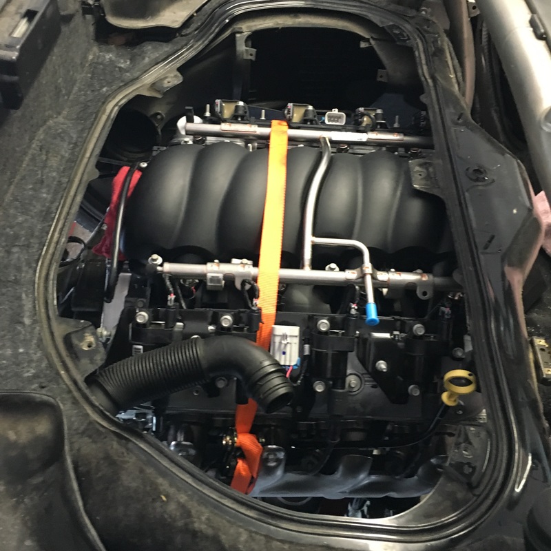
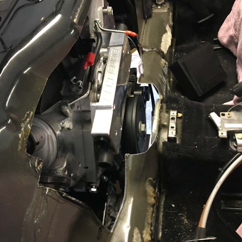
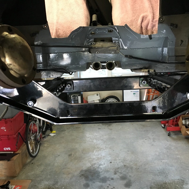
Well.... we finally did it! Turns out some more fabrication was in order due to my car having the newer transmission (which translates to larger) and required some special cutting and welding to accommodate it going into place behind the LS3. This will be a short update with just a couple of photos of the final installation and the engine fully supported on its own! No more engine lifts in the photos - YES!!! It's hard to see in this photo, but the oil pan and transaxle are fully above the the new engine cradle and frame rails - this menagerie of frames, braces, links and struts has to be assembled around the engine as it hovers in the space supported by a lift table.... whew Next are several photos of the transaxle mounts we had to fabricate - you'll notice it is the stock mounts cut and sectioned which we added a one inch thick wall pipe enabling them to be rewelded with both an offset to the rear of inch along with lowering the geometry Here's a couple of views from the top followed by photos of the front of the engine in its new "ride along with you in the cabin" position (lol) Next it is onto a ton of plumbing and wiring and computer programming to do - sure would like to drive it onto the field at Oktoberfest rather than trailer it:-)
Sty tuned and check back for updates soon!!! Thanks, Doug
1 Comment
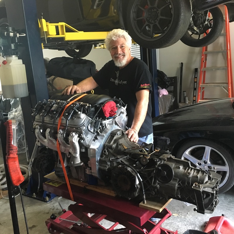
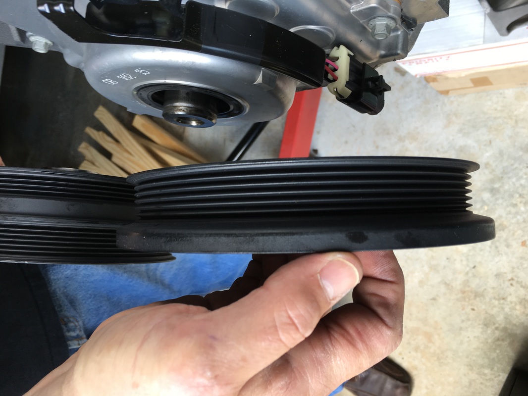
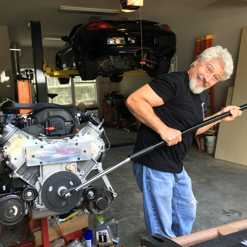
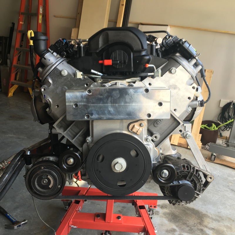
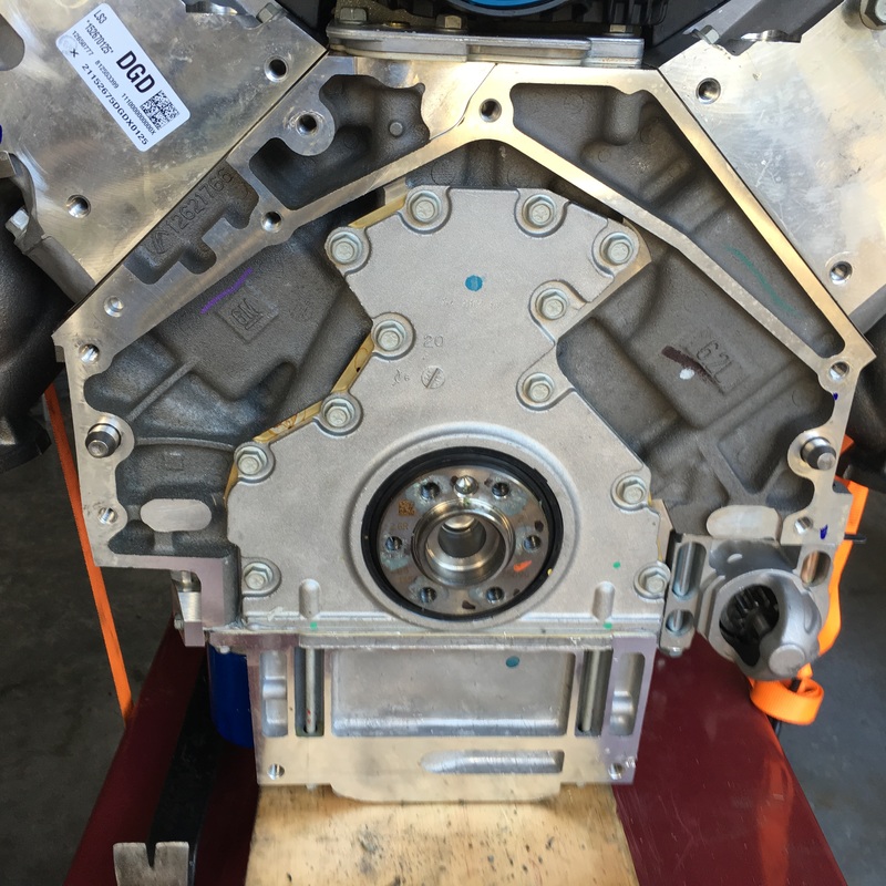
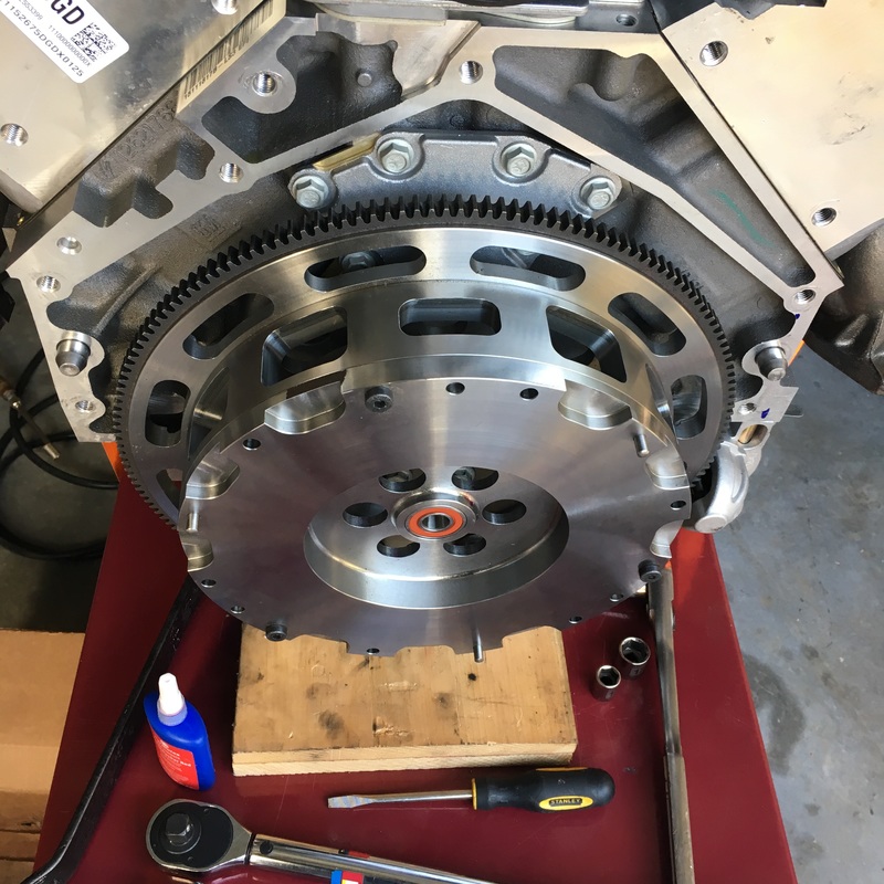
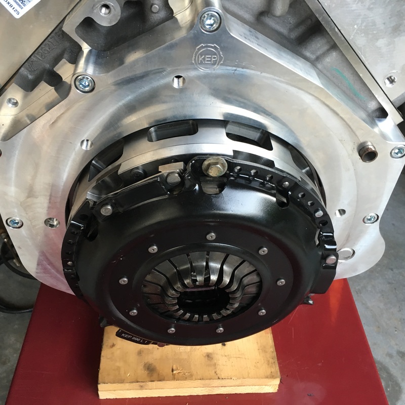
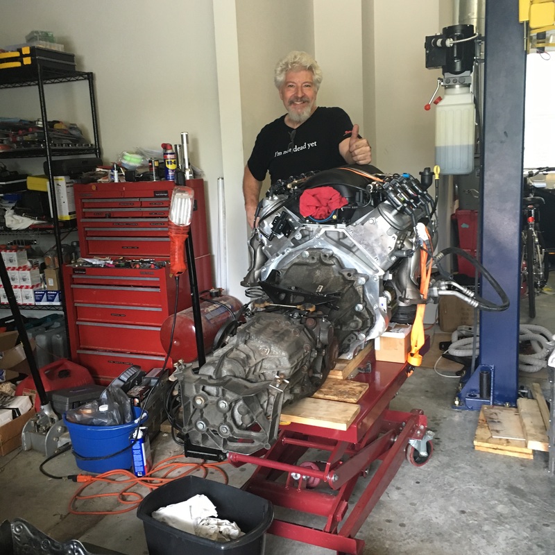
Well.... finally.... all the engine modifications have been made (extensive) and it's time to put it in the engine bay! But first - a little about that process. The right way to get a Boxster's engine in or out is with a lift table combined with a car lift (regardless of what engine is in the car:-) And it's a tricky operation with combinations of lift tabling up and car lift lowering... and twisting and shoving and lots of odds and ends to maneuver around while hooking up other plumbing and electrical that can only be reached at certain moments in the transition upward - ugh! BUT before we get to there... we have to finish dressing the motor up with a new slimmer crank pulley, add the the alternator and AC compressor and of course install the clutch and transaxle! Here's the slimmer pulley we're going to install compared to the stock Corvette pulley And here's the installation process... the bolt is a one time use bolt that is torqued to 100 ft/lbs and then continued to rotate for 240 degrees - you can do this! This bolt is stretch set rather than ft/lbs Here's the front of the engine with the two accessories (that's all that will fit) and belt in place. Now to the opposite end of the engine... the flywheel first. Here's photos of it going on Now the adapter plate & clutch - it's a stage 1 high performance clutch rated for 650 horsepower Sooooo... here we go! The the fully dressed drivetrain goes on the lift table and rolled under the car (which is up on lift) Now the tricky stuff... lowering the car while lifting the table and wiggle, twist, shout, cuss.... Here's the front of the engine; very close to the firewall we cut out & moved several inches forward FINALLY! a view from the top with the engine in place Here's a view of how much engine comes into the passenger compartment to ride with you:-) In case you were wondering... here's a photo of the cradle that will hold the motor mounts as well keep the car's unibody from racking (hopefully) under all that torque and horsepower! So that's it for this installment of the Blog... and of course I had to take the engine back out as the transaxle mounts would not line up - so back to the fabrication drawing board & try it again!!!!! Thanks for visiting and reading.... and keep checking back as there will be MORE! |
AuthorDoug Behning Archives
January 2019
Categories |

 RSS Feed

